A circuit in Physics is a closed loop or path that allows electrons to flow, creating an electric current. The basic components of a circuit include a power source (like a battery), conducting wires, a switch, and a device like a light bulb.
There are many types of circuits, such as:
- Series circuits
- Parallel circuits
- Star-delta circuits
- Linear and non-linear circuits
- Unilateral and bilateral circuits
- Closed and open circuits
- Series-parallel circuits
- DC (Direct Current) circuits
- AC (Alternating Current) circuits
Each type of circuit has unique properties and is used in different applications.
In this Physics article, we will explore various types of circuits, their characteristics, and how they are applied in everyday life. Additionally, we will address some frequently asked questions to help you better understand the concept of circuits.
What is an Electric Circuit?
- An electric circuit is a closed loop that enables the flow of electrical current to power and control various devices and systems.
- It consists of different components that work together to allow the current to flow at specific levels of voltage, current, and resistance.
- In simple terms, an electric circuit provides a pathway for electricity to move and perform functions like lighting a bulb, running a fan, or powering electronic gadgets.
Types of Circuits
Circuits are mainly of 12 types, namely:
- Open Circuit: A broken or incomplete circuit where no current flows.
- Closed Circuit: A complete electrical loop where current flows uninterrupted.
- Series Circuit: A circuit where components are connected in a single, continuous loop, sharing the same current.
- Parallel Circuit: A circuit where components are connected across multiple paths, sharing the same voltage.
- Series-Parallel Circuit: A combination of series and parallel circuits, offering both shared current and voltage paths.
- DC Circuit: A circuit where current flows in one direction, powered by a direct current source like a battery.
- AC Circuit: A circuit powered by alternating current, with current periodically reversing direction.
- Star-Delta Circuit: Used for transforming a star configuration to a delta configuration in electrical networks, commonly in motor starters.
- Linear Circuit: A circuit where the relationship between current and voltage is linear, following Ohm’s Law.
- Non-linear Circuit: A circuit where current and voltage do not have a linear relationship, often containing diodes or transistors.
- Unilateral Circuit: Allows current to flow in only one direction, like in a diode.
- Bi-lateral Circuit: Allows current to flow in both directions, commonly seen in resistive circuits.
For competitive exams such as SSC, Railway, UPSC, and various state-level exams, we focus on discussing the first eight types of circuits. These are considered the most fundamental and frequently form the basis of questions in competitive exams. Mastering these types is crucial for success, as they represent the foundational concepts in electrical circuits.
Closed Circuit
What is a Closed Circuit?
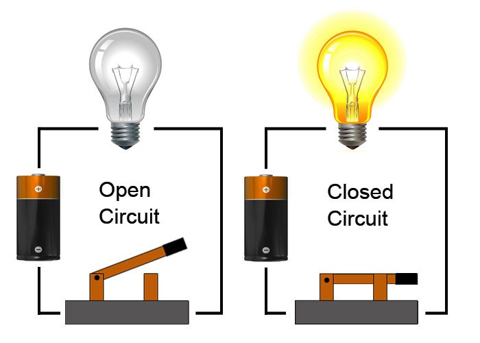
A closed circuit is an electrical circuit where the path for the current is complete, meaning the circuit is unbroken, and electricity can flow through it. In other words, the switch is “ON,” and the current has a continuous path from the power source to the device and back.
Key Features of a Closed Circuit
- Complete Path for Current: The current flows in a continuous loop, allowing electrical devices to work.
- Current Flow: Current can only flow in a closed circuit because there are no interruptions in the path.
- Devices Function: When the circuit is closed, devices like lights, fans, and motors will operate.
- Battery Power: The battery or power source in the circuit provides energy for the current to flow.
Diagram of a Closed Circuit
Advantages of a Closed Circuit
- Device Operation: In a closed circuit, all devices will work as intended, as the current has a continuous path.
- Efficient Energy Use: Power is fully utilized because the current can flow without interruption.
- Safety: The closed circuit is easy to control because the flow of electricity is predictable when the switch is closed.
Disadvantages of a Closed Circuit
- Risk of Overload: If too many devices are connected, the circuit may become overloaded and cause a short circuit or damage the components.
- Fixed Path: Once the circuit is closed, the current will follow the fixed path unless the switch is turned off.
Examples of Closed Circuits
- A flashlight when the switch is turned on.
- Household electrical appliances like fans, refrigerators, and lights when switched on.
- Simple electrical experiments where current needs to flow to power a device.
FAQs
Q1: What happens if the circuit is open instead of closed?
A: If the circuit is open, the current cannot flow, and the electrical device will not work.
Q2: Can a closed circuit be dangerous?
A: Yes, if too many devices are connected or the wires are not properly insulated, it can lead to overheating or a short circuit.
Q3: How do you know if a circuit is closed?
A: A closed circuit has a continuous path for current to flow, and the switch is in the “ON” position.
Quick Tip for Competitive Exams
- In a closed circuit, current flows because the circuit is unbroken, allowing devices to work.
- If the circuit is open, the current stops, and devices will not work.
Open Circuit
What is an Open Circuit?
An open circuit is an electrical circuit where the path for the current is incomplete or broken. This means the switch is in the “OFF” position, and electricity cannot flow through the circuit. Because of the break in the path, electrical devices in the circuit will not function.
Key Features of an Open Circuit
- Broken Path: In an open circuit, the electrical path is interrupted or broken, preventing current from flowing.
- No Current Flow: Since the path is open, no electrical current can flow through the circuit.
- Devices Do Not Function: Devices such as lights, fans, or motors will not work in an open circuit.
- Switch in “OFF” Position: An open circuit is often caused when the switch is turned off, creating a gap in the path.
Diagram of an Open Circuit

Advantages of an Open Circuit
- Safety: When the circuit is open, no current flows, which helps prevent overheating or potential damage.
- Control: Open circuits allow users to control when electrical devices are powered on or off.
Disadvantages of an Open Circuit
- No Operation: Devices connected to an open circuit will not function because there is no current flow.
- Inefficient: Since the circuit is open, electrical energy cannot be used to power devices.
Examples of Open Circuits
- A light switch turned off, preventing the light bulb from turning on.
- A broken wire or disconnected battery in an electrical setup.
- A television that is turned off, creating an open circuit.
FAQs
Q1: Why does the current stop in an open circuit?
A: The current stops because the path for the electricity is broken, and there is no continuous loop for the current to flow.
Q2: How can an open circuit be fixed?
A: To fix an open circuit, the break in the path needs to be closed, such as turning the switch on or repairing any damaged wires.
Q3: Can an open circuit be dangerous?
A: An open circuit is usually not dangerous, but if the circuit is intentionally left open to stop current flow, it helps in preventing damage or overload.
Quick Tip for Competitive Exams
- In an open circuit, the current does not flow because there is a break in the path, and devices will not work.
- If the circuit is closed, current flows, and electrical devices function normally.
Short Circuit
What is a Short Circuit?
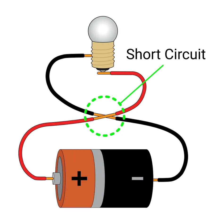
A short circuit is an electrical fault that occurs when there is an unintended connection between two points in a circuit, allowing electricity to flow through a shorter path than intended. This usually happens when two wires (positive and negative) touch each other, allowing the current to bypass the rest of the circuit.
Key Features of a Short Circuit
- Unintended Connection: In a short circuit, two conductors (typically the positive and negative wires) make direct contact, creating an easy path for current to flow.
- High Current Flow: The short circuit causes a sudden surge of electrical current, which can be very high and may lead to damage.
- Potential Damage: Short circuits can cause sparks, fires, or damage to electrical devices or wiring due to excessive current flow.
Diagram of a Short Circuit
Causes of Short Circuits
- Damaged Wires: When wires are exposed to wear and tear, the insulation may break, causing the wires to touch and create a short circuit.
- Loose Connections: Improper or loose connections between wires can result in a short circuit.
- Faulty Equipment: Malfunctioning electrical appliances or devices can lead to short circuits.
Danger of Short Circuits
- Overheating: The large current flow due to a short circuit can cause wires to heat up, potentially leading to fire hazards.
- Damage to Devices: Electrical devices, batteries, and circuits may get damaged or destroyed due to excessive current.
- Electric Shocks: In severe cases, a short circuit can cause electric shocks to anyone in contact with the system.
How to Prevent Short Circuits
- Proper Insulation: Ensure that wires are properly insulated and not exposed to wear and tear.
- Check Connections: Regularly check the connections and fix any loose or damaged parts.
- Use Circuit Breakers: Install circuit breakers or fuses in the system to automatically disconnect the current when a short circuit occurs.
Examples of Short Circuits
- A frayed wire touching another wire or metal surface, creating a direct connection.
- A faulty appliance with internal wiring issues causing a short circuit.
- Wires in contact with water or moisture that creates a short circuit by providing an alternate path for current flow.
FAQs
Q1: What happens during a short circuit?
A: During a short circuit, electricity flows through an unintended path, leading to a sudden increase in current that can cause damage or even fires.
Q2: How can we fix a short circuit?
A: To fix a short circuit, you need to disconnect the power source and check for damaged wires or faulty connections. The affected components should be repaired or replaced.
Q3: Are short circuits dangerous?
A: Yes, short circuits can be very dangerous as they can cause electrical fires, damage to electrical devices, or even electric shocks.
Quick Tip for Competitive Exams
- A short circuit happens when two wires or points that should not be connected touch, allowing current to flow through an unintended path, often causing damage and overheating.
Series Circuit
What is a Series Circuit?
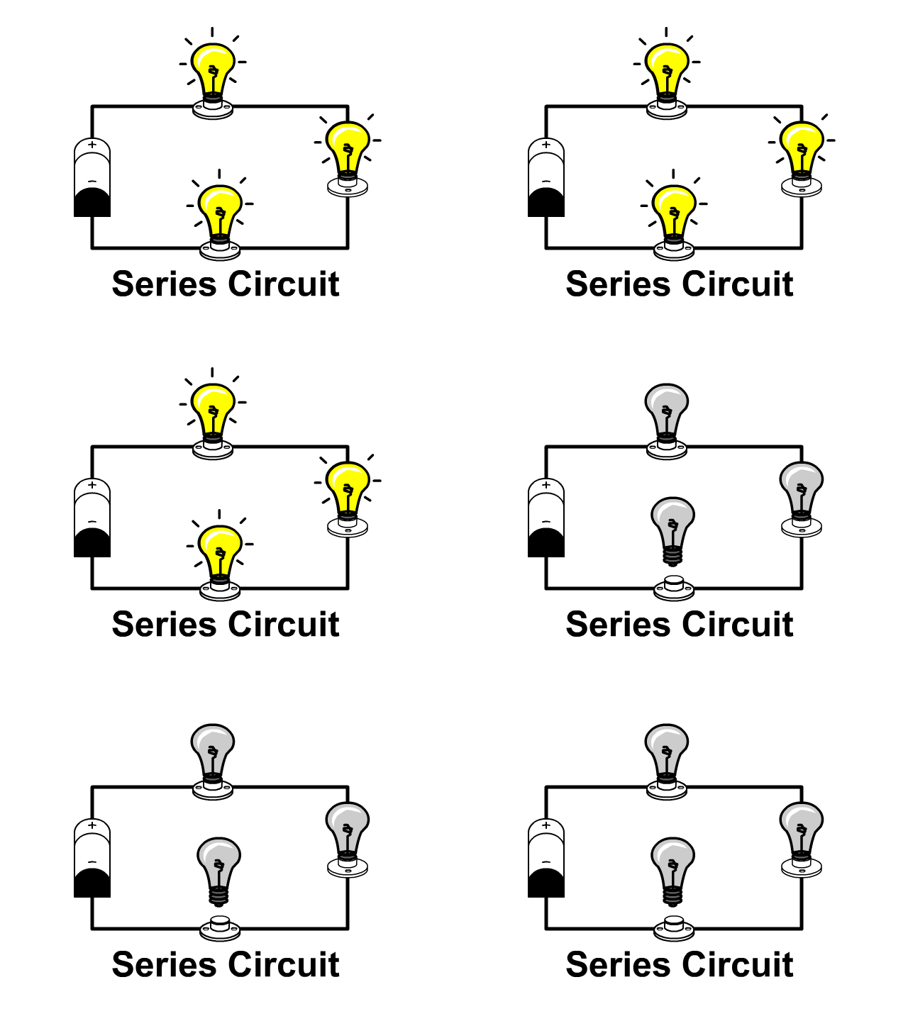
A series circuit is a type of electrical circuit where components are connected one after the other in a single path. The current flows through each component without branching or dividing.
Key Features of a Series Circuit
- Single Path for Current: All components share the same current as the current flows through them one by one.
- Voltage Division: The total voltage of the source is divided across all the components in the circuit.
- Resistors in Series: When resistors are connected in series, their resistances add up.
R total=R1+R2+R3+⋯+Rn
- Current is Constant: The same current flows through every component in the circuit.
- Open Circuit Effect: If any component is removed or breaks, the entire circuit stops working.
Diagram of a Series Circuit
Advantages of a Series Circuit
- Simple to Design: Easy to connect components in a single path.
- Cost-Effective: Fewer wires and connections are needed.
Disadvantages of a Series Circuit
- Failure of One Component: If one component fails, the entire circuit stops working.
- Voltage Distribution: Components receive different voltages, which may not be ideal for all devices.
Examples of Series Circuits
- Christmas lights (older designs).
- Battery-powered flashlights.
- Fuse-based safety circuits.
FAQs
Q1: What happens if one bulb burns out in a series circuit?
A: If one bulb burns out, the entire circuit is broken, and all bulbs stop working.
Q2: Why is the current the same in a series circuit?
A: In a series circuit, there is only one path for current to flow, so it remains the same through all components.
Q3: How do you calculate total resistance in a series circuit?
A: Add the resistances of all the components together.
Rtotal=R1+R2+R3……+Rn
Quick Tip for Competitive Exams
Remember, in a series circuit:
- The current is constant.
- The voltage adds up across components.
- The total resistance increases with more resistors.
Parallel Circuit
What is a Parallel Circuit?
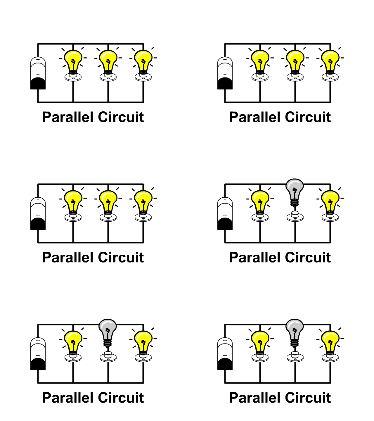
A parallel circuit is a type of electrical circuit where the components are connected in multiple paths. The current can flow through more than one path, allowing electricity to reach different components at the same time.
Key Features of a Parallel Circuit
- Multiple Paths for Current: In a parallel circuit, the current can split and flow through different paths.
- Voltage is Constant: The voltage across each component is the same as the source voltage.
- Resistors in Parallel: When resistors are connected in parallel, the total resistance decreases.
1/ Rtotal=1/R1+1/R2+1/R3+⋯+1/Rn
- Current Division: The total current is divided between the different paths based on the resistance of each path.
- Independent Components: If one component fails, the rest of the circuit still continues to work.
Diagram of a Parallel Circuit
Advantages of a Parallel Circuit
- Independent Operation: If one component fails, the rest will still function normally.
- Same Voltage: All components receive the same voltage, which is ideal for devices like light bulbs.
- Flexibility: Easy to add or remove components without affecting the overall circuit.
Disadvantages of a Parallel Circuit
- Complex to Design: More wires and connections are needed than in a series circuit.
- Higher Current Demand: The total current increases with more components, which may need a stronger power source.
Examples of Parallel Circuits
- Home electrical wiring (lights, fans, appliances).
- Christmas lights (modern designs).
- Household devices with multiple components working at the same time (TV, refrigerator, etc.).
FAQs
Q1: What happens if one component fails in a parallel circuit?
A: If one component fails, the other components will continue to work because they are on separate paths.
Q2: Why is the voltage the same in a parallel circuit?
A: In a parallel circuit, all components are connected directly to the voltage source, so they all get the same voltage.
Q3: How do you calculate total resistance in a parallel circuit?
A: Use the reciprocal formula. For two resistors, it’s:
1/Rtotal=1/R1+1/R2 + 1/R3 …… +1/ Rn (n= 1,2,3,4,5,6…….)
For more resistors, keep adding the reciprocals of each resistance.
Quick Tip for Competitive Exams
Remember, in a parallel circuit:
- The voltage is the same across all components.
- The current divides between the branches.
- The total resistance decreases with more resistors.
Series-Parallel Circuit
What is a Series-Parallel Circuit?
A series-parallel circuit is a combination of both series and parallel circuits in one system. It is used when you need to control multiple components and provide different voltage and current values across the circuit.
In this circuit, some components are connected in series, while others are connected in parallel. This combination allows for more flexible control over the current and voltage in the circuit.
Key Features of a Series-Parallel Circuit
- Combination of Series and Parallel: Some parts of the circuit are connected in series (end-to-end), and some are connected in parallel (side-by-side).
- Multiple Paths for Current: While the series part allows current to flow through a single path, the parallel part gives multiple paths for current to flow, depending on the circuit design.
- Voltage and Current Distribution: In the series part, the voltage is divided among the components, while in the parallel part, the voltage across each component remains the same, but the current divides.
Diagram of a Series-Parallel Circuit
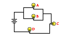
Working of a Series-Parallel Circuit
- Series Part: In the series section, components are connected one after the other. The total resistance increases, and the same current flows through each component.
- Parallel Part: In the parallel section, components are connected side-by-side. The total resistance decreases, and the voltage across each component is the same, but the current divides depending on the resistance.
Advantages of a Series-Parallel Circuit
- Flexible Voltage and Current: This circuit allows different voltages across components and ensures the current is controlled in specific parts of the circuit.
- Improved Control: By combining series and parallel circuits, you can control multiple components with ease, providing better efficiency for complex devices.
- Reliability: Since some components are connected in parallel, if one component fails, the other parallel components will continue to work.
Applications of Series-Parallel Circuits
- Home Appliances: Many home appliances use series-parallel circuits to distribute power efficiently to various components like lights, fans, or heating elements.
- Automobiles: Electrical systems in vehicles use series-parallel circuits for battery management, lights, and other electronic components.
- Computers: Circuits inside computers may use this combination to control power distribution and ensure proper functioning of multiple devices simultaneously.
Example of a Series-Parallel Circuit
- A flashlight: A flashlight may use a series circuit to connect the battery and switch, while the light bulbs inside it may be arranged in parallel to ensure they all get the same voltage.
FAQs
Q1: What is the main advantage of a series-parallel circuit?
A: The main advantage is the ability to control the voltage and current separately in different parts of the circuit, making it more flexible and reliable.
Q2: Can I use a series-parallel circuit to save power?
A: Yes, by distributing current and voltage efficiently, a series-parallel circuit can help in reducing energy loss and improving the overall efficiency of electrical devices.
Q3: How do I calculate the total resistance in a series-parallel circuit?
A: You calculate the total resistance by first solving for the series and parallel parts separately. For series, add the resistances; for parallel, use the formula 1/Rtotal=1/R1+1/R2+⋯
Quick Tip for Competitive Exams
- A series-parallel circuit combines the features of both series and parallel circuits, offering flexibility in voltage distribution and current control, commonly used in complex electrical systems.
AC Circuit
What is an AC Circuit?
An AC circuit is a type of electrical circuit powered by Alternating Current (AC). In an AC circuit, the direction and magnitude of the current change periodically, unlike Direct Current (DC), where the flow of current is constant in one direction.
In an AC circuit, the electric current alternates its direction, meaning it flows back and forth, changing its polarity. The most common source of AC power is the electrical grid used in homes and industries worldwide.
Key Features of an AC Circuit
- Alternating Current (AC): The current continuously changes direction and magnitude in a cyclic manner.
- Sinusoidal Wave: The current in an AC circuit often follows a sinusoidal waveform, which is a smooth, repeating wave pattern.
- Frequency: The number of cycles the AC current completes in one second is called the frequency, measured in Hertz (Hz). In India, the frequency is typically 50 Hz.
- Voltage: The voltage in an AC circuit also varies in polarity and magnitude in a sinusoidal manner.
Basic Components of an AC Circuit
- Source: An AC generator or the power supply (like your electricity provider) provides the alternating current.
- Resistor (R): A component that resists the flow of current and dissipates energy in the form of heat.
- Capacitor (C): A component that stores and releases electrical energy in the form of an electric field. It can change the phase of current and voltage in the circuit.
- Inductor (L): A component that stores energy in the form of a magnetic field and can also change the phase between current and voltage.
- Load: Any device or component that consumes electrical power, like a light bulb, fan, or motor.
Working of an AC Circuit
- Current Flow: In an AC circuit, the direction of current constantly changes, with the electrons moving back and forth. This reversal of direction happens at a regular frequency.
- Voltage Changes: The voltage also alternates, and it rises and falls in a smooth sinusoidal wave pattern, which is essential for powering most electrical devices.
- Energy Transfer: The components in the AC circuit (like resistors, capacitors, and inductors) interact with the AC current in different ways, either by storing energy, releasing energy, or resisting the flow of current.
Key Parameters of an AC Circuit
- Peak Voltage (V_peak): The maximum voltage reached during one cycle.
- RMS Voltage (V_RMS): The Root Mean Square (RMS) value of voltage, which is the effective voltage that delivers the same power as a DC voltage.
- Impedance (Z): The total opposition to current flow in an AC circuit, similar to resistance in a DC circuit but includes both resistance and reactance (due to inductors and capacitors).
- Phase Angle: The phase difference between the voltage and current in an AC circuit, especially important when dealing with capacitors and inductors.
Types of AC Circuits
- Purely Resistive AC Circuit: In this type, only resistors are present. The current and voltage are in phase, meaning they peak at the same time.
- Inductive AC Circuit: An AC circuit with only inductors. The current lags the voltage by 90 degrees, meaning the current reaches its peak later than the voltage.
- Capacitive AC Circuit: An AC circuit with only capacitors. The current leads the voltage by 90 degrees, meaning the current reaches its peak before the voltage.
- RLC Circuit: A combination of Resistor (R), Inductor (L), and Capacitor (C) in an AC circuit. The behavior of current and voltage depends on the values of resistance, inductance, and capacitance.
Applications of AC Circuits
- Power Distribution: AC circuits are used in power grids to distribute electricity to homes, industries, and businesses.
- Household Appliances: Most household appliances like refrigerators, air conditioners, televisions, and fans operate on AC power.
- Motors: AC motors are widely used in industrial machines and household appliances because of their ability to run on alternating current.
- Transformers: AC circuits are used in transformers to step up or step down voltage levels, making long-distance power transmission more efficient.
Advantages of AC Circuits
- Efficient Power Transmission: AC can be transmitted over long distances with minimal energy loss by using transformers to adjust voltage levels.
- Easier to Generate: Generating AC is simpler and more cost-effective than DC.
- Variable Voltage and Current: The voltage and current in AC circuits can be easily controlled, making them adaptable for different uses.
FAQs
Q1: What is the difference between AC and DC?
A: In AC (Alternating Current), the current alternates direction, while in DC (Direct Current), the current flows in a single direction only.
Q2: Why is AC used for power transmission?
A: AC is used because it can be easily transformed to different voltage levels, allowing for efficient long-distance transmission with minimal loss of energy.
Q3: How does the current behave in an AC circuit with inductance?
A: In an AC circuit with inductance, the current lags behind the voltage by 90 degrees due to the magnetic field created by the inductor.
DC Circuit
What is a DC Circuit?
A DC circuit is an electrical circuit powered by Direct Current (DC), where the current flows in a constant direction, unlike Alternating Current (AC), where the current changes direction periodically. The flow of current in a DC circuit is steady, which makes it suitable for many applications, especially where a stable voltage and current are required.
The most common source of DC power is a battery, where the positive terminal is connected to the load and the negative terminal to the ground or the return path of the circuit.
Key Features of a DC Circuit
- Direct Current (DC): In a DC circuit, the current always flows in one direction. This flow is steady and does not reverse.
- Constant Voltage: The voltage in a DC circuit remains constant, meaning it does not vary like AC voltage.
- Power Source: Common sources of DC include batteries, solar cells, and DC generators.
- Current Flow: The flow of current is from the positive terminal of the power source to the negative terminal.
Basic Components of a DC Circuit
- Power Source (Battery): Provides the constant voltage that drives the flow of current through the circuit.
- Resistor (R): Resists the flow of current, causing the energy to be dissipated as heat. It limits the amount of current in the circuit.
- Capacitor (C): A device that stores electrical energy and releases it when needed. In DC circuits, capacitors charge up and store energy.
- Inductor (L): Stores energy in the form of a magnetic field. In DC circuits, inductors oppose sudden changes in current.
- Load: The device that consumes electrical power, like a light bulb, motor, or any other electrical appliance.
Working of a DC Circuit
- Constant Current Flow: In a DC circuit, the current flows in a single direction. The electrons in the wire move from the negative terminal of the power source to the positive terminal.
- Energy Transfer: The electrical energy from the power source is transferred through the circuit components (resistor, capacitor, etc.), and the load converts it into another form of energy like light or motion.
- Voltage and Current: The voltage across components like resistors remains constant, and the current flow depends on the resistance in the circuit according to Ohm’s Law.
Key Parameters of a DC Circuit
- Voltage (V): The potential difference that causes the current to flow in the circuit. In a DC circuit, the voltage is constant.
- Current (I): The flow of electric charge through the circuit. It remains steady in a DC circuit.
- Resistance (R): The opposition to the flow of current. It determines how much current will flow for a given voltage.
- Power (P): The rate at which electrical energy is consumed or produced by a device in the circuit. In a DC circuit, power is calculated as P = V × I.
Applications of DC Circuits
- Battery-Powered Devices: Many portable electronic devices like smartphones, laptops, and flashlights use DC circuits powered by batteries.
- Solar Power Systems: Solar panels generate DC electricity, which is then used to power DC appliances or converted to AC for grid use.
- Electric Vehicles (EVs): The motors in electric vehicles run on DC circuits supplied by batteries.
- Low Voltage Systems: DC circuits are used in systems requiring low voltage, such as computer circuits, microcontrollers, and other electronic components.
Advantages of DC Circuits
- Steady Current: The current in a DC circuit remains constant, which makes it ideal for devices that require a stable power source.
- Easy to Store: DC power can be easily stored in batteries, unlike AC, which requires more complex systems for storage.
- Used in Electronics: Most electronic devices, such as mobile phones and laptops, use DC power for their operation.
FAQs
Q1: What is the main difference between DC and AC?
A: In DC (Direct Current), the current flows in one direction, while in AC (Alternating Current), the current reverses direction periodically.
Q2: What is the advantage of using DC in electronic devices?
A: DC provides a steady and constant flow of current, which is ideal for powering sensitive electronic devices that require stable voltage.
Q3: What is Ohm’s Law in DC circuits?
A: Ohm’s Law states that Voltage (V) = Current (I) × Resistance (R). It helps to calculate the relationship between voltage, current, and resistance in a DC circuit.
Types of Circuits FAQs
In an open circuit, the resistance is infinite. This is because there is a break or gap in the circuit, which prevents current from flowing, and thus, the resistance becomes immeasurably high.
In home electrical wiring, a parallel circuit is used. This allows multiple appliances to be connected and operated independently while maintaining a constant voltage across all devices.
In a series circuit, the current remains the same across all components, but the voltage is divided among them according to their resistance.
A rectifier is used to convert alternating current (AC) to direct current (DC). It allows current to flow in only one direction, thus converting AC to DC.
AC circuits (alternating current circuits) have a frequency, which refers to the number of cycles of alternating current per second. The frequency is measured in hertz (Hz).
A DC circuit (direct current circuit) is used in torchlights. They run on batteries, which supply direct current for powering the bulb.
Diwali decorative rice lights are typically connected in a series circuit, where the lights are connected end to end, and the same current flows through each light.
In a short circuit, the current flows through a very low resistance path, often bypassing the load. This can lead to excessive current flow, damaging electrical appliances and potentially causing fires.


