Have you ever wondered how electricity flows through wires? Ohm’s Law is a simple rule that explains the relationship between voltage (V), current (I), and resistance (R) in an electric circuit. It helps us understand how electric devices like bulbs, fans, and mobile chargers work.
According to Ohm’s Law, when we increase the voltage, the current also increases—just like when we push water through a pipe with more force, more water flows. This law is very important for competitive exams like SSC, Banking, RRB NTPC, UPSC, and other state-level exams under General Science (Physics).
In this guide, we will learn about the statement, formula, and real-life applications of Ohm’s Law in an easy and exam-focused way! 🚀
What is Ohm’s Law?
Ohm’s Law is one of the fundamental principles of electricity and circuits, discovered by German physicist Georg Simon Ohm. It explains the relationship between voltage (V), current (I), and resistance (R) in an electrical circuit.
Ohm’s Law Definition
👉 Ohm’s Law states that the voltage (V) across a conductor is directly proportional to the current (I) flowing through it, provided that the temperature and other physical conditions remain constant.
This means that when the voltage increases, the current also increases, and when the voltage decreases, the current decreases, as long as the resistance remains the same.
Ohm’s Law Formula
The mathematical expression of Ohm’s Law is: V=I×RV = I \times RV=I×R
Where:
✔ V = Voltage (Volts)
✔ I = Current (Amperes)
✔ R = Resistance (Ohms, Ω)
Three Formulas to Calculate Current, Voltage, and Resistance
- To calculate Voltage: V=I×RV
- To calculate Current: I=V/R
- To calculate Resistance: R=V/I
These formulas help in solving numerical problems related to electric circuits in competitive exams like SSC, UPSC, RRB NTPC, and Banking.
Ohm’s Law Equation
According to Ohm’s Law: V∝I
(Voltage is directly proportional to current) V=R×I
(Where R is a constant for Ohmic conductors)
This means if we increase the voltage, the current increases proportionally, and if we decrease the voltage, the current decreases proportionally.
Explanation of Ohm’s Law with Diagram
Let’s take a simple example:
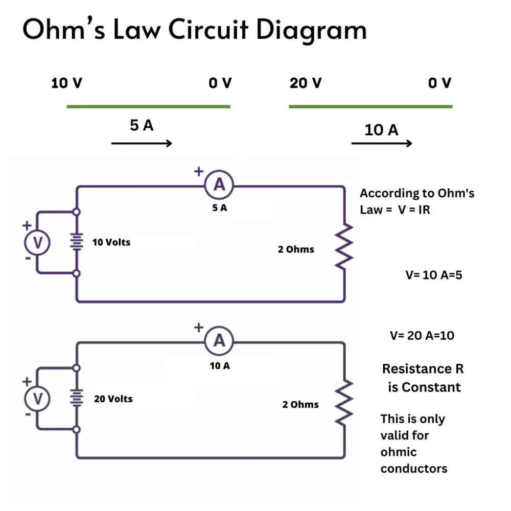
🔹 Suppose a metal wire has a potential difference of 10V (Volts) applied across it, and a current of 5A (Amperes) flows through it.
🔹 Now, if we increase the potential difference to 20V, the current will also increase to 10A because of the stronger push of electrons.
🔹 This shows that current is proportional to voltage, proving Ohm’s Law.
Key Takeaways from Ohm’s Law
✅ If voltage increases, current increases (if resistance is constant).
✅ If resistance increases, current decreases (if voltage is constant).
✅ Used in designing electric circuits, appliances, and electrical safety systems.

Experimental Verification of Ohm’s Law
Ohm’s Law states that voltage (V) is directly proportional to current (I) in a conductor, provided the temperature remains constant. This principle can be verified through a simple experiment using basic electrical instruments.
Instruments Required for Ohm’s Law Experiment
To perform this experiment, you will need the following:
✔ Voltmeter – Measures the potential difference (V) across the resistor.
✔ Ammeter – Measures the electric current (I) flowing through the circuit.
✔ Resistor – Provides constant resistance (R).
✔ Rheostat – Adjusts the current flow in the circuit.
✔ Battery – Supplies the required voltage.
✔ Plug Key – Acts as a switch to control the circuit.
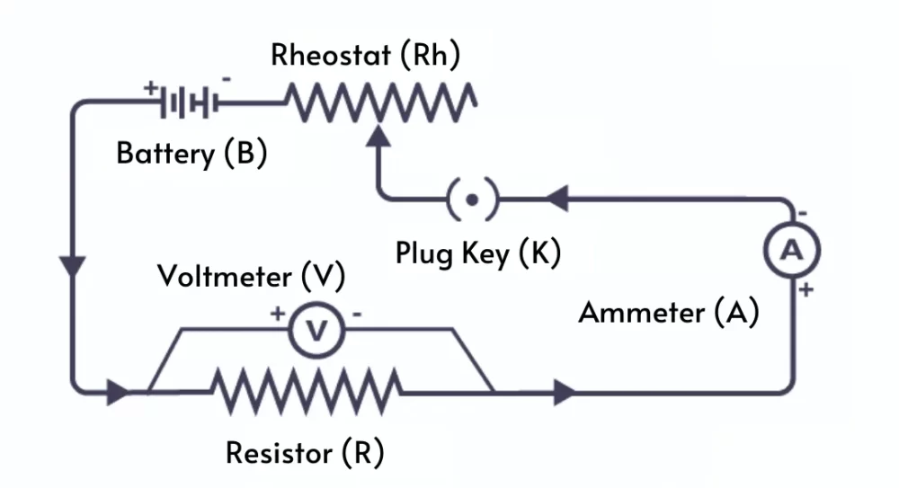
Circuit Diagram for Ohm’s Law Experiment
📌 The experimental setup includes:
- A battery connected to a resistor in series.
- An ammeter is connected in series to measure the current.
- A voltmeter is connected in parallel across the resistor to measure the voltage.
- A rheostat is used to control the current.
- A plug key is used to start and stop the circuit.

Procedure of the Experiment
🔹 Step 1: Close the plug key (K) and adjust the rheostat to obtain the minimum readings on the ammeter (A) and voltmeter (V).
🔹 Step 2: Slowly increase the current using the rheostat and record the corresponding values of voltage (V) and current (I) from the voltmeter and ammeter.
🔹 Step 3: Repeat the process multiple times to obtain different voltage and current readings.
🔹 Step 4: Calculate the ratio V/I for each set of readings.
🔹 Step 5: You will notice that the ratio V/I is almost constant in every case, proving that V/I = R, which remains unchanged.
Graphical Representation of Ohm’s Law
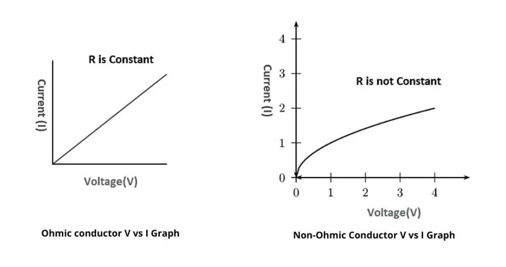
📌 If you plot a graph of voltage (V) on the Y-axis and current (I) on the X-axis, you will get a straight line.
✔ A straight-line graph confirms that current (I) is directly proportional to voltage (V), verifying Ohm’s Law.

✅ The experiment proves that as voltage increases, current increases proportionally, confirming Ohm’s Law: V=I×RV = I \times RV=I×R
To stay updated with the latest GK and Current Affairs infographics, follow our official Instagram and Facebook page and prepare for exams easily.
Limitations of Ohm’s Law
Ohm’s Law is a fundamental principle in electrical circuits, stating that V = IR (Voltage = Current × Resistance). However, it has several limitations when applied to certain electrical components and materials. Below are the key limitations of Ohm’s Law explained in detail:
1. Not Applicable to Non-Ohmic Components
Ohm’s Law is valid only for ohmic conductors, where the ratio of voltage to current remains constant. However, for non-ohmic materials like diodes, transistors, and thermistors, this ratio changes with voltage and temperature.
2. Fails for Unidirectional Components
- Ohm’s Law does not hold for components like diodes and transistors, which allow current to flow in only one direction.
- These components exhibit a non-linear relationship between voltage and current, making Ohm’s Law ineffective.
3. Not Suitable for Non-Linear Electrical Elements
- Devices with varying capacitance, resistance, or inductance exhibit time-dependent behavior, violating the constant V/I ratio assumed by Ohm’s Law.
- Examples include semiconductors, vacuum tubes, and varistors, where resistance changes under different voltage or current conditions.
4. Cannot Be Used for High-Frequency AC Circuits
- Ohm’s Law does not apply to AC circuits with inductors and capacitors, where phase differences between voltage and current exist.
- In such cases, reactance and impedance must be considered instead of simple resistance.
5. Ineffective for Superconductors and Insulators
- In superconductors, resistance becomes zero at critical low temperatures, making Ohm’s Law invalid.
- Insulators do not allow current flow under normal conditions, contradicting the linear relationship defined by Ohm’s Law.
6. Not Valid for Heating Elements
- Filaments in light bulbs and heating elements (e.g., tungsten filament) experience resistance variation with temperature, leading to deviations from Ohm’s Law.
While Ohm’s Law is essential for understanding basic electrical circuits, it has several limitations in real-world applications. Engineers and physicists use more advanced concepts, such as non-linear circuit analysis and semiconductor physics, to describe the behavior of modern electrical components.
Calculating Electrical Power Using Ohm’s Law
Electrical power is the rate at which electrical energy is transferred within a circuit. It is measured in Watts (W) and can be calculated using Ohm’s Law and different combinations of voltage (V), current (I), and resistance (R).
Formula for Electrical Power
1. When Voltage and Current Are Given:
P=V×IP = V \times I
2. When Voltage and Resistance Are Given:
P=V2RP = \frac{V^2}{R}
3. When Current and Resistance Are Given:
P=I2×RP = I^2 \times R
These formulas allow us to calculate power efficiently based on available values in an electrical circuit.
Understanding the Power Triangle
The power triangle is a visual representation that helps determine electrical power, voltage, and current when two of these values are known.
Power Triangle Representation:
- P (Power) is placed at the top.
- V (Voltage) and I (Current) are at the bottom.
- Using this triangle, you can derive formulas for different values:
Power, Voltage, and Current Formulas from the Triangle

✔ Power (P) Formula → Given voltage (V) and current (I): P=V×I
✔ Current (I) Formula → Given power (P) and voltage (V): I=PV
✔ Voltage (V) Formula → Given power (P) and current (I): V=PI
By using Ohm’s Law and the power triangle, you can easily determine the power, voltage, or current in an electrical circuit. These formulas are essential for electrical engineering, circuit analysis, and practical applications in electrical devices.
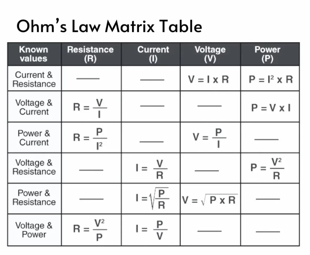
Ohm’s Law Matrix Table
Ohm’s Law relates four key electrical parameters: Voltage (V), Current (I), Resistance (R), and Power (P). The Ohm’s Law Matrix Table provides a structured way to determine the value of any one parameter when two others are known.

Key Applications of Ohm’s Law
Ohm’s Law is a fundamental principle in electrical engineering and circuit analysis. It plays a crucial role in determining voltage (V), current (I), and resistance (R) in various electrical and electronic applications.
1. Calculating Voltage, Current, and Resistance in Circuits
- Ohm’s Law is used to find unknown electrical parameters in a circuit when two values are known.
- Engineers and electricians use it for circuit design, troubleshooting, and optimization.
2. Determining Voltage Across a Resistor
- Ohm’s Law helps compute the voltage drop across a resistor in both series and parallel circuits.
- This is essential for ensuring proper current flow and preventing circuit damage.
3. Maintaining Voltage Drop Across Electronic Components
Ohm’s Law ensures that the correct voltage drop is maintained across various electronic and electromechanical components, including:
✔ Capacitors & Inductors – To regulate energy storage and discharge.
✔ Diodes & Transistors – To control signal flow in electronic circuits.
✔ Oscillators – To maintain stable frequency output.
✔ Relays & Switches – To manage current flow in control circuits.
✔ ICs & Connectors – To ensure stable power distribution in microelectronics.
4. LED Circuit Design
- Ohm’s Law is used to calculate the appropriate resistor value to protect an LED from excessive current.
- Ensures LEDs operate within their safe voltage and current limits to prevent burnout.
5. Application in DC Ammeters and Shunts
- Ohm’s Law is used in DC ammeters to measure current and in DC shunts to divert excess current safely.
- This helps in precise current measurement in electrical devices and power systems.
Ohm’s Law is a vital tool for electrical engineers, hobbyists, and circuit designers. From basic circuit calculations to complex electronic applications, its principles are widely used to ensure safe and efficient electrical operations.
FAQs
Answer: The flow of direct current is directly proportional to the potential difference and inversely proportional to the resistance of the circuit.
Answer: Georg Simon Ohm
Answer: Ohm
Answer: R = V ÷ I (Voltage divided by current)
Answer: Ohm’s law is important because it states the relationship between voltage, current, and resistance.